Nice discussion.. taken from..
http://control.com/thread/1232811875
The primary purpose of the Stop-Ratio Valve (SRV) is to serve as the gas fuel stop valve. The secondary purpose is to regulate the fuel pressure upstream of the Gas Control Valve (GCV), particularly during starting and acceleration, but also during rated speed operation.
Consider the typical situation where the gas fuel supply pressure is approximately 15-20 barg. Note that the gas fuel pressure required at the gas fuel nozzles in the turbine during starting is only approximately 0.2-.035 barg. If there were just one control valve, unless that control valve was a very special control valve (which translates into a very expensive control valve) it would only be open a couple of mm, at best, and the ability of that valve to reduce and control the downstream pressure from 20 barg to 0.2-0.35 barg would be very severely limited. Establishing flame and controlling fuel flows during acceleration would be very difficult with many types of single control valves.
So, the SRV serves to drop the pressure upstream of the GCV to about 2.0 barg (the exact value is site-specific!) during starting, and increases the pressure as a function of turbine speed, until the unit reaches rated speed (Full Speed-No Load, FSNL, for a generator drive application). At that point the gas fuel pressure reference is 100% (since the speed is 100%).
With a significantly lower pressure upstream of the GCV uring firing (establishing flame in the combustors) the GCV can be opened to a position where it's much easier to control the flow through the valve (and the downstream pressure); the same is true for acceleration of the unit to rated speed.
Now, when the turbine is synchronized and loaded, the GCV opens to increase fuel flow to the combustors. This increased fuel flow tends to cause the pressure upstream of the GCV to drop, but the SRV will open slightly to maintain the pressure reference as the GCV is opened.
As load is reduced, the GCV closes and the pressure upstream of the GCV tends to increase but the SRV closes slightly to maintain the pressure reference as the GCV is closed.
So, the pressure downstream of the GCV will change as the unit is loaded and unloaded and started and accelerated (and decelerated). But the SRV will move to whatever position it needs to in order to maintain the required pressure reference upstream of the GCV. The SRV regulator is *NOT* a position loop; it is a pressure loop with position control for indication and stability. The SRV moves to whatever position is required to try to maintain the pressure upstream of the GCV equal to the pressure reference (which is a function of turbine speed).
Also, if the gas fuel supply pressure were to increase during steady-state turbine operation the pressure upstream of the GCV would tend to increase, but the SRV will close slightly to maintain the pressure equal to the reference. The opposite is true if the gas pressure decreases. I've been at many sites where the SRV is at 100% stroke (full open) because the gas fuel supply pressure is much lower than it should be, and usually the power output of the turbine is also lower than desired (because it can't get enough fuel).
Finally, on a more typical style control valve if the upstream pressure is known and/or is controlled to a specific value or range then the flow through the control valve is more linear with respect to stroke and can be controlled by controlling the position (stroke) of the control valve. That's another really important benefit of the SRV/GCV system. (Note, that on most GE-design heavy duty gas turbines the Speedtronic does *not* monitor or control either the gas fuel flow-rate or the pressure downstream of the GCV! This reduces the complexity of the control system required to control gas fuel flow, but also puts some requirements on the system that is used to control gas fuel flow. That's where the flow-versus-stroke relationship becomes important.)
Now, there are single valves which could have been used, but back when GE was first developing their heavy duty gas turbines those valves were extremely expensive and very difficult to interface with. GE probably decided to use two more typical valves in the staged configuration in order to reduce cost as well as to reduce the complexity of the control system.
Good question; hope this helps!
02 October 2012
31 August 2012
Modbus data packet size
reference used.. http://langhofer.at/fileadmin/downloads/sineaxcam/Modbus_Basics.pdf
Modbus RTU packet..

Modbus TCP packet...

Modbus RTU packet..

Modbus TCP packet...

Byte and Word swap when dealing with 32 bits (4 Bytes) Modbus data
Note 1 – Article used as reference
Note 2 - Software used as reference
FPconverter from http://www.61131.com
Modbus protocol was designed
based on devices with a 16-bit register length. Consequently, special
considerations were required when implementing 32-bit data elements. This
implementation settled on using two consecutive
16-bit registers to represent 32 bits of data or essentially 4 bytes of
data.
Big-Endian is the most
commonly used format
for network protocols – so common, in fact, that it is also referred to as
‘network order’.
As a rule of thumb, the family of a device’s microprocessor
determines its endianness. Typically, the big-Endian
style (the high-order byte is
stored first, followed by the low-order byte) is generally found in CPUs designed with a Motorola processor. The little-Endian style (the low-order byte is stored first,
followed by the high-order byte) is generally
found in CPUs using the Intel architecture.
System integrator has to be very careful when dealing with 32
bits Modbus data. Various manufacturers may implement various data swapping
techniques as described in table below:
|
Swap Mode
|
Source
Bytes
|
Target
Bytes
|
||
|
None
|
AB
|
CD
|
AB
|
CD
|
|
Byte and
Word swap
|
AB
|
CD
|
DC
|
BA
|
|
Byte
swap
|
AB
|
CD
|
BA
|
DC
|
|
Word
swap
|
AB
|
CD
|
CD
|
AB
|
24 August 2012
RS485 2-wire connection diagram
taken from...
http://www.bb-elec.com/tech_articles/485_2wire_connection_illustration.asp
this is the most common wiring diagram for serial connection to field instruments especially for Modbus RTU purposes..

http://www.bb-elec.com/tech_articles/485_2wire_connection_illustration.asp
this is the most common wiring diagram for serial connection to field instruments especially for Modbus RTU purposes..

21 August 2012
Calculation methods of compressibility factor for natural gas
Taken from...
Calculation methods of compressibility factor
- AGA 8 Detailed Characterization Method - Required parameters are:
- Pressure
- Temperature
- Gas mixture components fractions or percentages
Reference: American Gas Association Report No. 8, "Compressibility Factor of Natural Gas and Other Related Hydrocarbon Gases", Second Edition, November 1992, 2nd printing July 1994. Detail Characterization Method.
- Pressure
- Temperature
- Gross caloric (heating) value
- Relative density (specific gravity)
- Fraction or percentage of carbon dioxide
Reference: American Gas Association Report No. 8, "Compressibility Factor of Natural Gas and Other Related Hydrocarbon Gases", Second Edition, November 1992, 2nd printing July 1994. Gross Characterization Method-1.
- Method 2
- Pressure
- Temperature
- Relative density (specific gravity)
- Fraction or percentage of carbon dioxide and nitrogen
Reference: American Gas Association Report No. 8, "Compressibility Factor of Natural Gas and Other Related Hydrocarbon Gases", Second Edition, November 1992, 2nd printing July 1994. Gross Characterization Method-2.
- NX19 mod. - Required parameters are:
- Pressure
- Temperature
- Relative density (specific gravity)
- Fraction or percentage of carbon dioxide or nitrogen
Reference: VDI/VDE 2040, part 2, 1987. Calculation principals for measurement of fluid flow using orifice plates, nozzles and ventury tubes. Equation and formulas.
- GERG-91 mod. - Required parameters are:
- Pressure
- Temperature
- Relative density (specific gravity)
- Fraction or percentage of carbon dioxide or nitrogen
Reference: ICO/TC 193 SCI No. 63. Natural gas - calculation of compression factor. Part 3: Calculation using measured physical properties.
- GPSA - Required parameters are:
- Pressure
- Temperature
- Relative density (specific gravity)
Reference: Gas Processors Suppliers Association, Engineering data book, 1998
11 August 2012
Modbus Serial vs TCP and DNP3 Serial vs TCP
Difference between Modbus Serial and Modbus TCP and DNP 3.0 Serial vs DNP 3.0 TCP... very straight forward explanation..
taken from...
http://controltoolbox.com/blog/2009/03/why_dnp_over_ip_is_smarter_tha.html
There are many aspects of DNP3 protocol that are superior compared with Modbus. However, I like to talk about DNP/IP and Modbus TCP specifically. Like Modbus, DNP was originally designed to cover a serial link. As IP becomes more popular, both DNP and Modbus add IP option to the core protocol. What DNP designers did was to just simply embed the DNP traffic in an IP envelop. Modbus designer modified the header and removed the CRC of the traditional Modbus message to migrate to Modbus TCP. I think they did that because they were thinking that TCP header already has a CRC and keeping the Modbus CRC is kind of redundancy.
Now, here is the problem with Modbus TCP. Lots of people have Modbus TCP masters and legacy Modbus devices. For them, connecting the master to the device requires more than a simple terminal server that converts IP traffic to serial. The reason is there would be a need for a gateway that can adjust the protocol from serial version to TCP version and vice versa. That’s why you see many manufacturers making devices called Modbus gateway. The situation with DNP is much simpler. Since the DNP packets in IP and serial version are the same, a simple terminal server can do the job. Terminal server gets the IP traffic and sends the DNP payload on the serial side. Conversely, it gets the DNP packets on the serial link and embeds in the IP envelopes to transmit over the IP link.
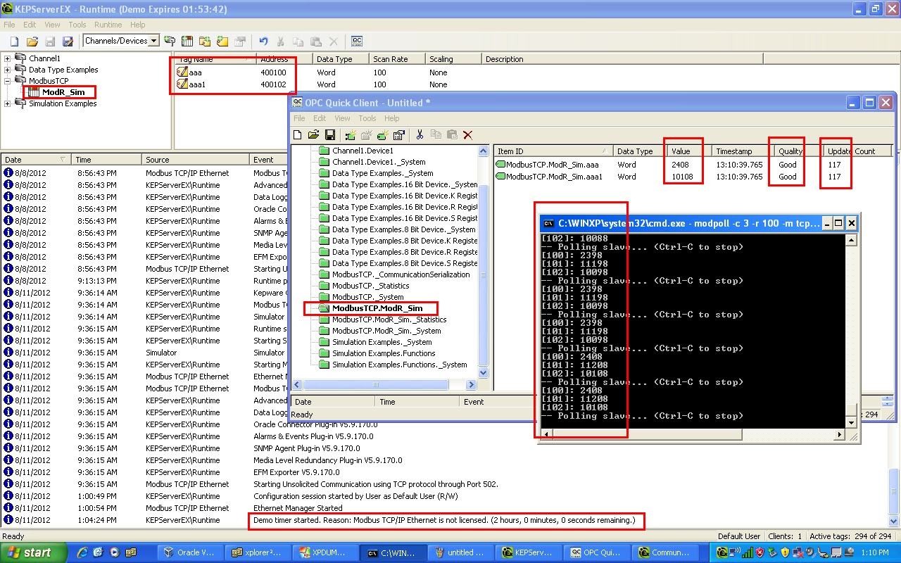
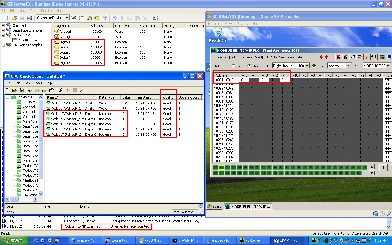
Successful Modbus TCP Simulation (Master and Slave) using Modpoll + KepserverEx + Mod_RSsim
had a chance to play with a powerful Modbus TCP/RTU simulator from Mod_RSsim.. the Mod_RSsim acts as Modbus TCP Master while Modpoll DOS application acts as Modbus TCP Client. I further tested with KepserverEx and manage to get the Modbust TCP OPC Server up and running !! Screenshots below for your reference...


18 April 2012
KLIA Yokogawa Centum CS List of I/O Card
1) ADM51C for digital input signals
2) ADM52C for digital output signals
3) ACM12 for serial communication with other sub-systems
4) AAM11 is for analog input signals
5) AAM51 is for analog output signals
6) AAM21 is for RTD signals
7) APM11 is for pulse signal, typically coming from devices like flow meter
14 April 2012
Mini Audit on LPP PI Enterprise Server
I visited LPP the week b4 raya and conducted some "mini audit" on their PI Enterprise System... conclusion... not so good.... below are my findings / comments..
1. Windows 2003 Server 32 Bit Standard Edition OS is used. Due to this version, the OS can only detect up to 3.5 GB of memory. This is a known limitation. I didnt check physically how much RAM is installed. If more than 4GB of RAM is installed, then the remaining RAM which is not "detected" is a waste.
See Microsoft notes below for reference,
http://msdn.microsoft.com/en-us/library/aa366778(v=vs.85).aspx#physical_memory_limits_windows_server_2003
I propose the OS to be upgraded to Enterprise Edition to overcome this issue. Also the trend nowadays is to use 64 Bit OS. See below for benefits of 64 Bit computing.
http://www.microsoft.com/middleeast/windowsserversystem/64bit/benefits.aspx
2. By doing "ipconfing" command, i notice that the server has 2 different NICs bcoz it is connected to 2 different networks ie. Office Network (192.168.1.X) and Data Source Network (192.168.0.X).
The Data Source Network is simply a network consisting Samsoft AP580 ABB P14 card and the PI Interface PC.
3. By performing a "traceroute" command, i notice that the PI server is behind a router which has IP address of 192.168.1.99. A quick check with Nik IT - this is a old Cisco router with NO firewall capabilities. Some risk here as the server is exposed. I didnt perform port query check to verify opened port on the server due to time and tools constraint.
Natural gas volume compressibility correction methods
When it comes to volume correction of natural gas, it refers to Pressure, Temperature and Compressibility aka "PTZ" correction.
P and T correction is rather straight forward as it is basically a ratio between Actual Value over Base Value.
Z correction is however a bit more complex. I wont go deep into this, but suffice at this moment to share that multiple methods / calculations are used in the industry as below:

P and T correction is rather straight forward as it is basically a ratio between Actual Value over Base Value.
Z correction is however a bit more complex. I wont go deep into this, but suffice at this moment to share that multiple methods / calculations are used in the industry as below:
Subscribe to:
Posts (Atom)